stereoscopic viewing
adding depth to 3d images has long been the holy grail of 3d modeling
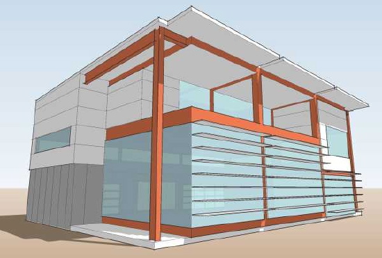
We have all experienced stereoscopic images. We have stereoscopic vision, so everyday sight is what I am talking about. The few inches between our eyes provide a slightly different view point. For any given surface that we see one eye sees a little bit more or a little bit less of it. While the difference is very slight it is sufficient for us to judge distances in 3d space. This is something we have not really been able to capture when we do drawings. While we have gotten pretty good at depicting 3d space the images don't create the sense of relative depth that our two eyes provide.
There have been many attempts to provide this vision to flat images, and we are pretty familiar with them I'm sure. With the advent of photography early on there were efforts to make 3d images with special viewers and cameras that took two images with the required offset. We have probably used a "View Master" image viewer which worked on the same principal. I'm sure that you have tried a blue/red filter glasses to view images or movies in 3d. These rely on the filters to deliver the proper image to each eye. More recently this has been done more effectively with polarizing filters on the projectors and viewers glasses. Sometimes the effect can be achieved by simply staring into the distance with the respective images directly in front of each eye.
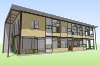
The two images below are such stereo images, each slightly offset from the other.
 Another way to put the images together into a 3d view does not require you to feed the right and left images discreetly to each eye. Its been found that if the right and left images are presented sequentially, alternating in the same space that your mind will read the spatial depth in a similar manner. If you click on the images above such a sequencing will load. The depth of field in this image will exaggerate the effect - it will look a bit like an earthquake but nothing that will make you nauseous!
Technorati Tags: house plans, modern design, modern house, Steel Case House
Continue reading "stereoscopic viewing"
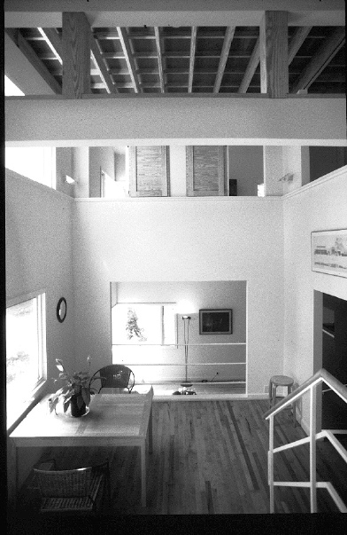
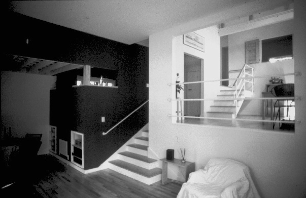 This gives you a good idea of how the spaces step down the hill and are interconnected. The next photo is from the guest room at the entry level in the front looking back towards the living room at the rear and the master bedroom above.
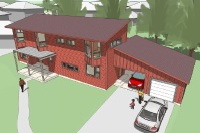
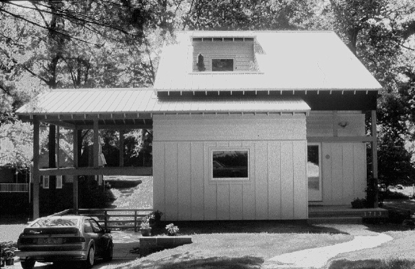
 And the exterior, the front of the house next:
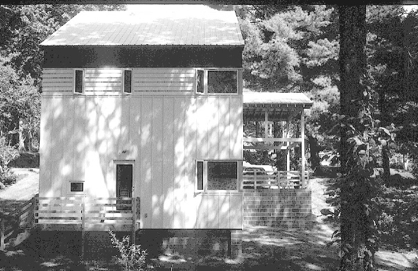
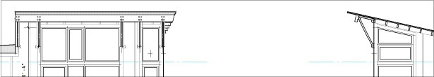
 and then the side, you can clearly see the hill side here:
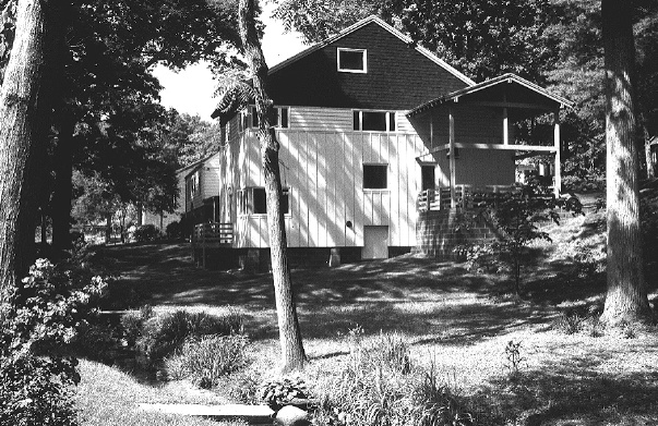 and finally the rear which overlooks the small stream and the garage and pavillion beyond.
 Thoughts and questions about the house are welcome. I want to convince Peter to do the work required to offer this as a stock plan.
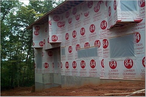
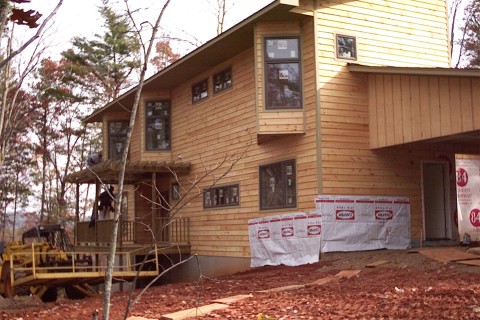 One thing I have not discussed relative to this instance of the Tray House is deviations from the plans. These things are immediately obvious to me, and I assume the design savvy readers here will also take note of these things. Deviations are going to be par for the course with stock plans and I don't really regard them with any criticism. I think it is valuable to consider the fall out of these changes however as they can have a ripple effect. If you think these things through you will know better how they affect other parts of the design. Sometimes these issues are purely technical, and sometimes aesthetic, but they tend to get tangled together.
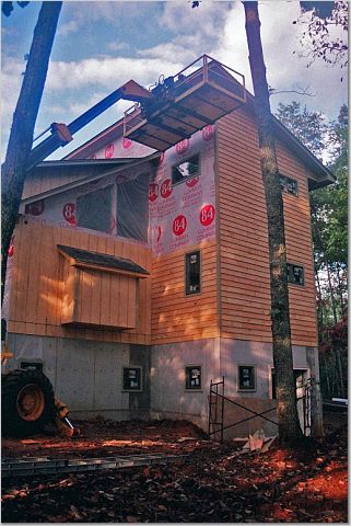
For example the builder of this house used roof trusses rather than roof rafters to frame the roof. That in of itself would not necessarily cause other changes, but somewhere in the process a decision was made to support the trusses that were above the bay windows on a header above the window rather than a beam spanning the entire bay window opening at the wall as specified. What this did was create a variety of span points in the trusses which I am guessing make it easier to make the trusses with the bottom cord extending all the way out under the eave. This created a horizontal eave where the design called for an eave that followed the roof slope. It also required headers to carry the roof load above the bay window units which now had to be pushed downward, almost to the floor to make room for them. Small decisions can propagate little changes in this way. We can always help you to think them through so you are satisfied with changes that may result.
One thing I have not discussed relative to this instance of the Tray House is deviations from the plans. These things are immediately obvious to me, and I assume the design savvy readers here will also take note of these things. Deviations are going to be par for the course with stock plans and I don't really regard them with any criticism. I think it is valuable to consider the fall out of these changes however as they can have a ripple effect. If you think these things through you will know better how they affect other parts of the design. Sometimes these issues are purely technical, and sometimes aesthetic, but they tend to get tangled together.
For example the builder of this house used roof trusses rather than roof rafters to frame the roof. That in of itself would not necessarily cause other changes, but somewhere in the process a decision was made to support the trusses that were above the bay windows on a header above the window rather than a beam spanning the entire bay window opening at the wall as specified. What this did was create a variety of span points in the trusses which I am guessing make it easier to make the trusses with the bottom cord extending all the way out under the eave. This created a horizontal eave where the design called for an eave that followed the roof slope. It also required headers to carry the roof load above the bay window units which now had to be pushed downward, almost to the floor to make room for them. Small decisions can propagate little changes in this way. We can always help you to think them through so you are satisfied with changes that may result.
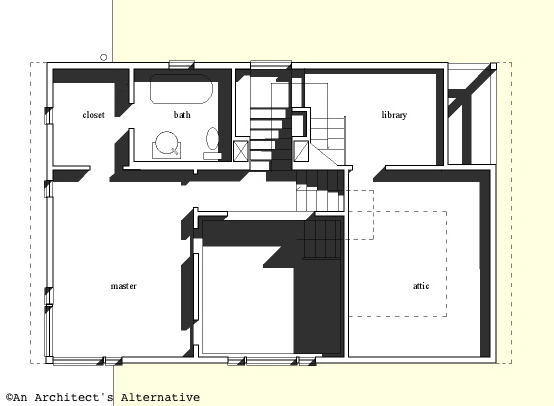
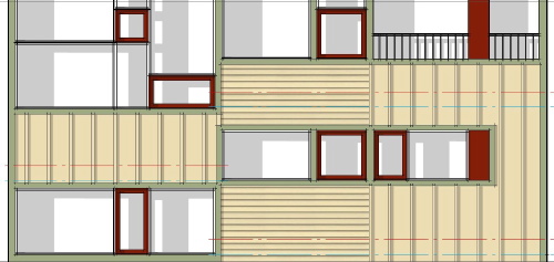
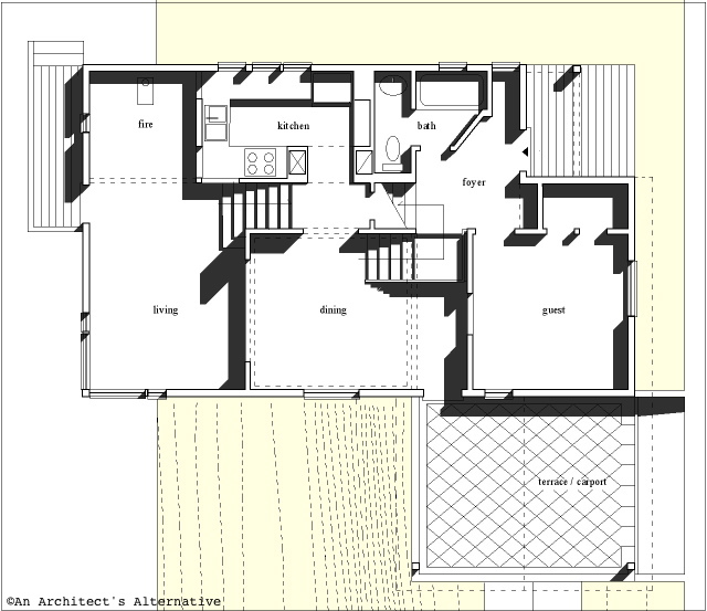 plan of the lower levels
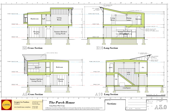
Peter has made a great study of Austrian architect Adloph Loos, and the design of this house reflects the multi-levels and intricately interwoven spaces that typify Loos' work. I find that I can look at this plan time and time again and be fascinated by imagining the spaces and moving through them. The section drawing below is a great aid in understanding the plan.
Peter built this house, could be 10 years ago, I don't remember exactly. He needed to be very efficient to meet his budget, and at the same time satisfy his creative drive. Essentially he was dealing with the same issues that we have at hand in trying to make modern more affordable. The overall treatment is contextual, but the use of cladding thoughtful, and the massing of the house unusual. The arrangement of the interior spaces is where the house is most fascinating.
plan of the lower levels
Peter has made a great study of Austrian architect Adloph Loos, and the design of this house reflects the multi-levels and intricately interwoven spaces that typify Loos' work. I find that I can look at this plan time and time again and be fascinated by imagining the spaces and moving through them. The section drawing below is a great aid in understanding the plan.
Peter built this house, could be 10 years ago, I don't remember exactly. He needed to be very efficient to meet his budget, and at the same time satisfy his creative drive. Essentially he was dealing with the same issues that we have at hand in trying to make modern more affordable. The overall treatment is contextual, but the use of cladding thoughtful, and the massing of the house unusual. The arrangement of the interior spaces is where the house is most fascinating.
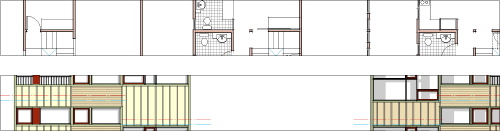
 plan of the middle levels
Why am I showing this? Because I love the house and want to share it here. Also because I am trying to convince Peter to offer the house as a stock plan through my site. As you know I have created all the designs on my site, and I have been reluctant to offer anybody else's designs as I would want the quality to be on a par with my own, and I am very critical in this regard. Peter's work is intellectually rigorous as well as grounded in construction. I would be thrilled to see his work on available as it would give him a lab for his ideas and allow us to see them executed on a wider basis.
plan of the middle levels
Why am I showing this? Because I love the house and want to share it here. Also because I am trying to convince Peter to offer the house as a stock plan through my site. As you know I have created all the designs on my site, and I have been reluctant to offer anybody else's designs as I would want the quality to be on a par with my own, and I am very critical in this regard. Peter's work is intellectually rigorous as well as grounded in construction. I would be thrilled to see his work on available as it would give him a lab for his ideas and allow us to see them executed on a wider basis.
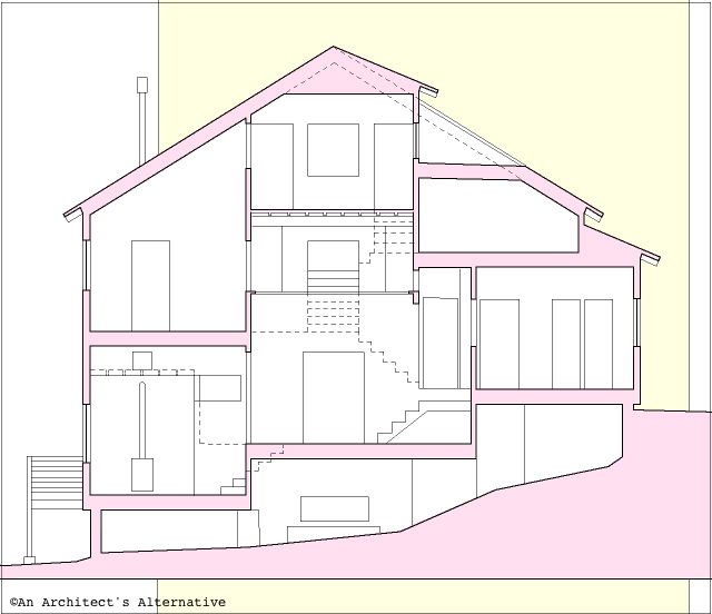 section drawing of the house
What can you do? Let me know what you think. If you don't understand the plans of the house, then ask me questions and I'll try to clarify. I will try to get photos from him of the exterior of the house as well, because after all this is already built.
section drawing of the house
What can you do? Let me know what you think. If you don't understand the plans of the house, then ask me questions and I'll try to clarify. I will try to get photos from him of the exterior of the house as well, because after all this is already built.
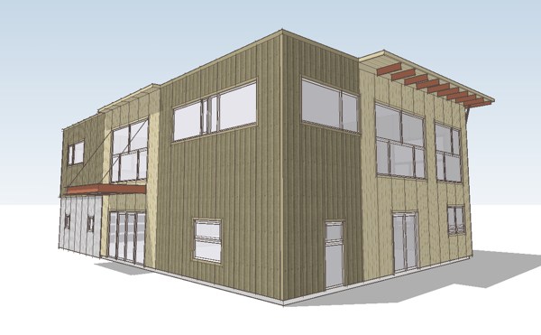
 Freed of the prototype's floor plan we were able to explore more of the potential of this approach.
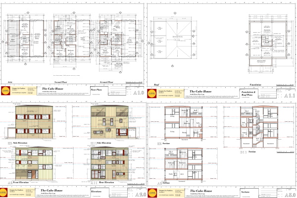
 The elevations for the first time in our Construction Prints will be in full color with a toned backdrop created from the 3dmodel of the house. I am enthusiastic about this as color really has a lot of power to clarify and convey information. This new technique is a real win/win as it is a time saver and results in better drawings.
 Inside the house is closed in. That means the drywall is up, and the joints are being finished. In order to do this all of the work behind the walls had to be completed since the last photos - all the electrical, plumbing, and HVAC rough in had to be completed and the entire house insulated. They are actually getting very close to being finished now.
 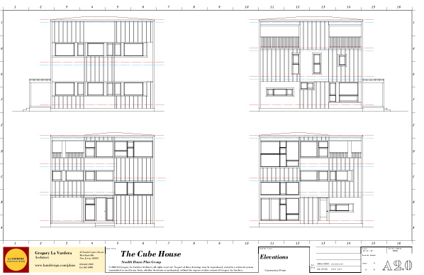 Thats it - the main sheets are all set up and I'll start developing them up now.
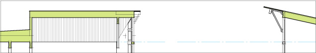
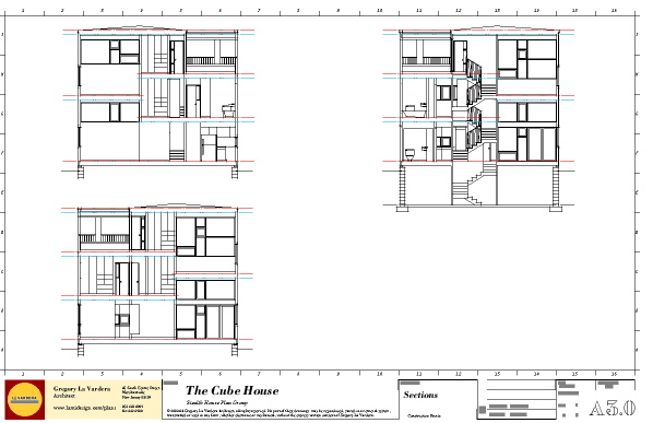 We are trying to leverage the work already done in the 3d model now by exporting the base lines for the section drawings directly from the 3d model. It saves drafting time and provides a better representation of a section through the house via all the detail in the 3d model.
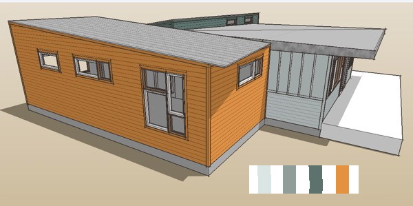 One of the color studies we did with Sara's colors.
I'll tell you - to me its humbling. Doing a good job with the design of the house is important no doubt, but it is just one part of the whole process. The factory, the on-site contractor, and as you will see, the client must be masterful with their roles as well.
One of the color studies we did with Sara's colors.
I'll tell you - to me its humbling. Doing a good job with the design of the house is important no doubt, but it is just one part of the whole process. The factory, the on-site contractor, and as you will see, the client must be masterful with their roles as well.
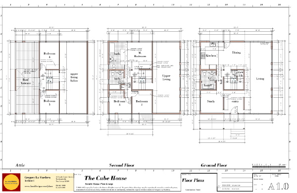
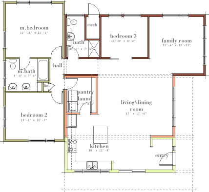
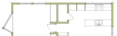
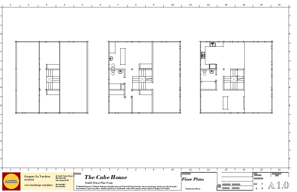 the floor plan sheet
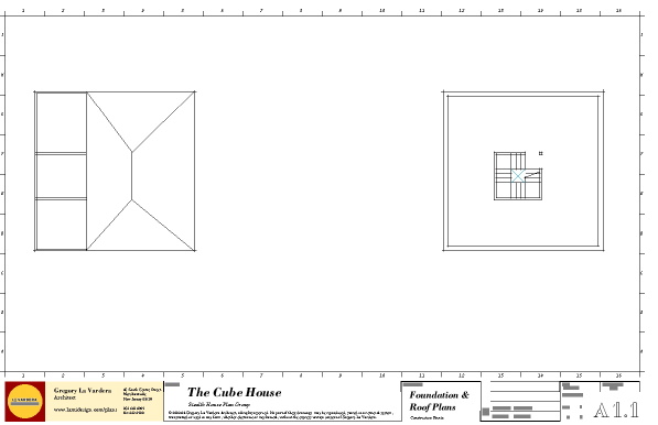 the roof and foundation plan sheet
In this case the foundation will be documented as a full basement, with crawl space or slab foundations a simple modification
the roof and foundation plan sheet
In this case the foundation will be documented as a full basement, with crawl space or slab foundations a simple modification
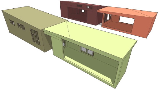
 The colors on the plan correspond to each modular section of the house. We had them tinted like this to convey how we planned them to be arranged for the factory floor and for transport as shown in this diagram.
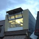
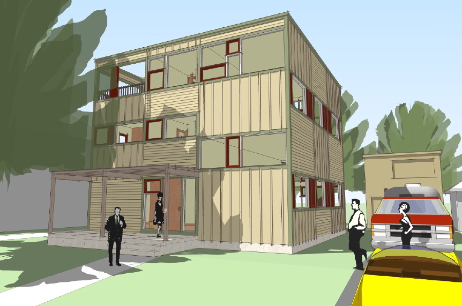
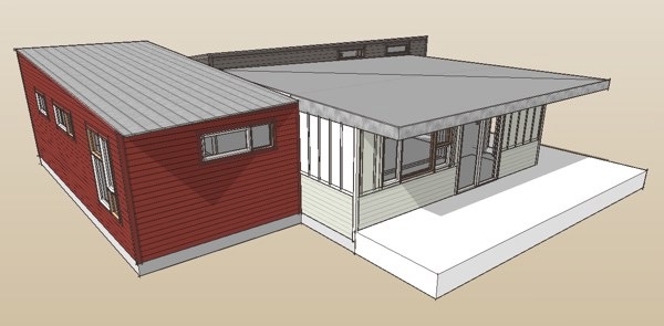
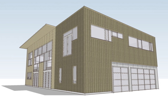
 The side of the house above faces towards the strret. The un-rendered white area will be a deck and porch that wraps around the corner of the house. The site has a side yard orientation, so the back and other side are treated more like side yards and the living space's connection to the outdoors is primarily from the side. The footprint is about 1400 sqft and based on sketches brought into the process by the clients. There are 3 bedrooms, two baths, and open plan kitchen dining living area, and a small family room area as well.
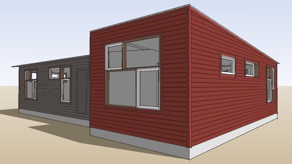 There are 4 modules, two containing the bedrooms and family room, and two that join to form the living and kitchen area. The four modules join in pairs to fit into two factory bays, and ship on two trailers. The roof heights are low to avoid the need for separate roof modules which would consume more factory space and more trailers/transport cost.
 I know everybody is going to want to know what it costs - they don't have final numbers yet. They are going to be doing a great deal of the finish work themselves on site with friends and family for labor - even modular building can not beat sweat equity. As I learn more I'll try to quantify it.
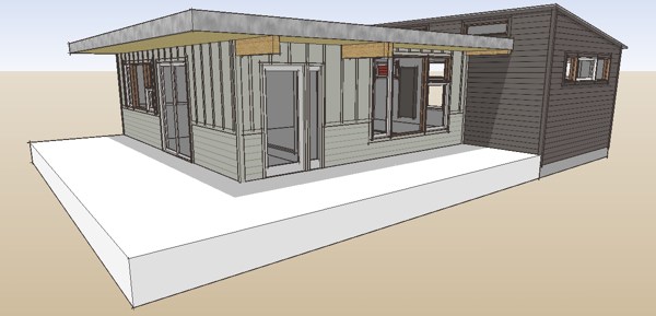
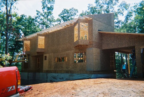 here the house all framed and sheathed
 and here under roof waiting for windows and siding
 I am collaborating with Northern to develop modern designs utilizing the EcoSteel system as we all agree that it is a natural for the given construction aesthetic of the system.
We don't have all the details yet as we are still working through this. Browse through the rest of the site and I think you will get a feeling for their business. I think this is a unique entry into this modern prefab movement. They already prefabricate and erect metal buildings nationwide so there is no warm-up period. Everything is in place and it should scale up immediately as demand warrants. I am interested in your feedback however and I can direct interested parties to the manufacturer.
I am collaborating with Northern to develop modern designs utilizing the EcoSteel system as we all agree that it is a natural for the given construction aesthetic of the system.
We don't have all the details yet as we are still working through this. Browse through the rest of the site and I think you will get a feeling for their business. I think this is a unique entry into this modern prefab movement. They already prefabricate and erect metal buildings nationwide so there is no warm-up period. Everything is in place and it should scale up immediately as demand warrants. I am interested in your feedback however and I can direct interested parties to the manufacturer.


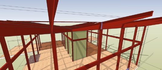
 This is a view of the same connection shown in my previous entry. A view like this can take the fear factor out of a detail.
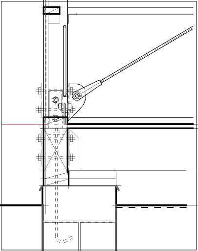 What's going on here. The perimeter beams are anchored down to the pier using conventional anchor bolts. The beam is connecting to the post with an inverted post cap connector from Simpson - the same kind is being used up top of the post as well. This connector has two vertical legs on each side of the post bolted thru with two 3/4" bolts. We are going to overlay that plate with an angle trimmed to serve as an anchor for the cleavis of our diagonal brace. This allows us to used the same bolts to attach this additional hardware. To bring the other diagonal brace in at the corner we have to have another angle offset in height so the bolts can cross without interference. The diagonal ties must be offset to the inside of the posts to allow them to pass the horizontal frames. A similar detail will resolve all the connections at the top of the post, and hopefully it will all look easy, and be easy to put together.
 Its been an amazing week. I get worn down with this pace so the enthusiasm that reaches me keeps me fresh and motivated. At the beginning of this week late in the day I was looking on the web for some ariel photos for a project site when there was knock at the office door. Once in a blue moon the ups guy has a bad day and can come really late so I did not think much of it being 5:30. I open the door and there is a fellow there looking with much interest up and down the outdoor stairway. He introduces himself as one of the people whom I have corresponded with about the house plans, his wife actually. The are from Philadelphia and were driving by my town and said they just had to stop to take a look at our office and he figured he would just knock. Knock me out is what he did! He was very full of enthusiasm for the stock plan effort and I have to admit that it all just caught me completely off guard. I made sure I had them on the mail list and by the time my head cleared it was time for them to run. I don't meet you all out there in person often enough and experiencing the emotion of another person first hand is a charge - I mean here was somebody else right here in flesh and bone who gets it, just like me. And so later this week I get an email inquiry from somebody very interested in the
 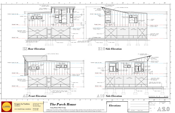 The section drawing is next. When that is complete I will develop the detailed wall sections for the house which were blocked out earlier. I am getting more and more excited about completing this project every day. This has been one of my favorites and it will be nice to finally see it "have wings". Some strong inquiries on the 0380 Cube House today look like they will drive that one to completion as well.
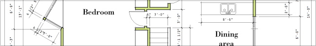 There is a logic to the way the dimension graphics go down. Plan dimensions around the perimeter are in a hierarchy, outside to in. Overall dimensions, then major breaks in the massing, then openings in the exterior envelope, then interior partitions that intersect the exterior walls.
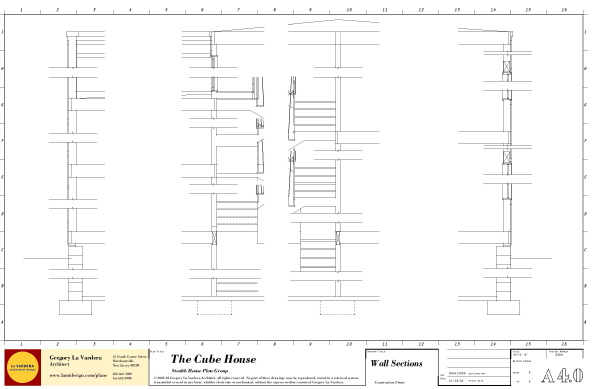
 Next the wall section drawings will be blocked out and the notations can begin following that.
 And now the elevations are in a similar state.
 on to the sections drawings