
Mock-Up of USA New Wall & Swedish Platform Framing
In mid February the founders of ByggHouse gathered in Rockford, Ill for a team meeting, and for a team building activity we undertook the construction of a mock-up of a nordic layered wall using American building materials and components.
the interior side layers
I've been describing this wall assembly in the talks I've given over the past few years, and I have multiple diagrams and several videos explaining the configuration of USA New Wall and Swedish Platform Framing. But at times having a physical mock-up speaks louder than words or drawings, so we set out to build the mockup you now see here.
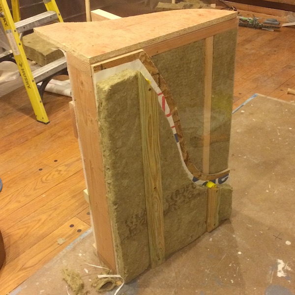
the outside layers
For the exterior layers we limited the continuous insulation to 1.25" to keep the bulk of the mock-up down. However this 1.25" of stone wool corresponds to R5 insulation value, which is the value for exterior insulation which is frequently called for in the IRC building code in order to meet the requirements of the most current energy codes. Given that, higher total insulation value can be attained with 2", 3", or 4" of continuous exterior stone wool.
Similarly we used at 2x6 stud wall assembly for the mock-up again to reduce the bulk. Into the stud cavities we fitted R23 Roxul stone wool. When higher insulation values are desired a 2x8 assembly would be used, which would accommodate R30 stone wool batts. Since the dimensions of our mock-up were reduced from actual construction we had to trim all of the insulation pieces to fit the odd sized cavity widths. And of course we did that with the SkarBord cutting table.
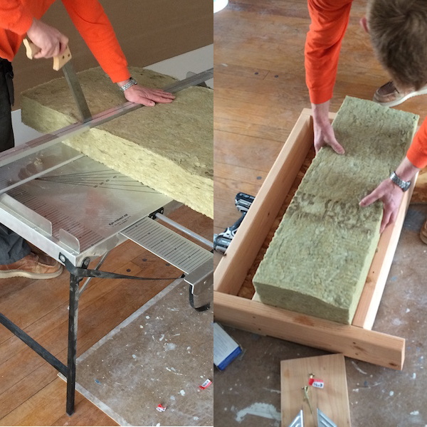
cutting with the SkarBord gives a perfect fit
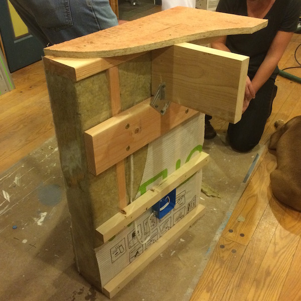
On the inside we can see the service cavity where all the wiring can run inboard of the vapor control and air sealing sheet. In this case we've used a sample of the Intello+ variable permeability membrane for the air sealing and vapor control sheet. Since all the electrical work is inboard of this sheet there is no need to make a hole in it for each light switch and receptacle which makes it much easier to make the house air-tight. Speaking of electrical work, one of the most frequent questions is how to install electrical boxes into this 1.5" service cavity. Simple, as you see here, a 4x4 box with a switch plate reducer cover handles typical devices, and is also available in double gang configurations. These boxes are a few cubic inches larger than typical single gang boxes, and actually give you a little bit more room to work. Up above you can see the ledger board which lives in the depth of the same service cavity, and once placed such allows us to keep the bearing end of our floor joists inside of the air tight sheet, and allows the main stud cavity insulation to extend all the way to the top of the joists.


It's interesting to see the mock-up built. It reminds me of Bensonwood's system, only with a little less material that should result in a lower cost. How does the order of construction work with this system if it's site-built? Does the interior insulation and vapor barrier get installed before upper floors or roof are built? If so, what protects the insulation and vapor barrier from getting wet or damaged during further construction? Is fire blocking necessary to keep a fire from spreading up the stud bays and into the floor system?
ReplyDeleteWhen site building, after the stud frames go up and before the ledger is mounted you need to apply a strip of the vapor sheet, with a hem to seal to the deck above, and a hem to tape to another sheet that will cover the wall below. The insulation behind the ledger and floor system has to be shoved up into that void from below. A bit of a pain, but that is what you get for site building.
DeleteNo wood fire blocking is required when using stone wool - it qualifies as fire blocking. Check the fire blocking section of the IRC for yourself.
This wall assembly seems like a great reduction in thermal bridging. For a story-and-a-half house with 16' tall balloon framed walls, could the wall cavities extend all the way from sill to top plates -- no fire blocks other than the Roxul -- and the second floor hung with joist hangers from a rim joist/ledger with the floor deck creating a platform that didn't extend out over a top plate as you've shown ? And what are the yellow plastic items hidden by the exterior Roxul in your photos ? Are they some sort of standoff to prevent the furring from compressing the Roxul ? If so, with them to maintain the spacing, couldn't the much less expensive comfort batts be used exterior as well as interior ?
DeleteFinally, what would you think of using EcoFoil radiant barrier as the interior vapor barrier in this assembly ? It seems like the interior wiring chase would allow a radiant barrier to function properly and improve heat retention.
I've never tried to detail a balloon frame version, but you would probably have to let the ledger in to the stud to get sufficient bearing, depending on your span. Swedish houses are small and so surface mounting the ledger works for them because the loads are light. Once you've let the ledger in you can cover it with the vapor sheet, but you will have to rely on face mounted joist hangers fastened through the vapor sheet.
DeleteThe yellow plastic piece is an upcoming ByggHouse product. Can't share any more detail till its out.
Not sure about radiant in place of a smart vapor control membrane. If summer cooling is used it could be as bad a poly vapor barrier.
I would have thought a let-in ledger as in classic balloon framing would also require the joists to be face nailed to the studs for lateral stability, because the ply doesn't include the rim joist, making a continuous vapor barrier difficult as well as requiring site-built walls. Would burying beams in the 2nd floor structure to keep spans short in wider rooms seem like a worthwhile trade off ? It would allow a simpler lagged ledger complete floor diaphragm (kept entirely inside the vapor barrier) for racking and lateral stability. Maintaining full cavity insulation depth sill-to-plate and minimizing thermal bridges is what appeals most to me about your New Wall, as well as being able to raise offsite completed wall panels.
DeleteI think the only way to really reduce span is smaller rooms. Embedding beams creates complexity that makes the trade off for simpler joist hanging moot. But this is also why I prefer the Swedish Platform approach over Balloon framing. First off you gain your decking fastened to the top plate of the wall for a stronger diaphragm, but for larger joist loads its easy to let the ledger into the top of the stud on the inside, topped by the single top plate. Now you can hang your joists off this with a top flange hanger, all put in place over the vapor control sheet. Then you use a 2x2 or 2x4 furring strip right below the joists for the place to screw the top of your drywall, and to tie the bottom of the joists together for stability. Platform is better than Balloon.
DeleteSee this image of a Swedish house being site built - not factory built:
Deletehttps://www.flickr.com/photos/lamidesign/15153477633/in/album-72157646930605133/
You can see the surface mounted ledger, face nailed, or screwed, and you can see how small the span is - small rooms.
Here you can see their method for letting a header/ledger in to the top of the studs:
https://www.flickr.com/photos/lamidesign/13307769255/in/album-72157646930605133/
Note this on the exterior of the stud because this is not a wall with joist bearing, just window headers, so this one is put towards the outside face, but same notching.
This is so common in Sweden that you can buy a saw to cut these notches in a single operation - dial in the dimensions, insert your stud, and the saw notches it perfectly:
http://www.randek.com/en/products/cut-saws/notching-saw-js400c
Is the reason to use the intello+ rather than a semi-permeable paint on the GWB just to keep that barrier from getting punctured every time someone hangs a picture on the wall or is it more to do with geography / AC use?
ReplyDeleteHere in the Seattle area you almost never see a membrane on the interior.
Also, I've been really interested in the wall system since I first came across it (on your blog) and would love to see a well documented project I could point to to encourage clients (and GCs) to try it out. Does one exist?
The reason to use the intello is because its a variable permeability membrane, so it will work well in a climate that is primarily heating, but uses cooling in the summer.
DeleteAs far as the position, the reason to have a wiring cavity is so the vapor control sheet stands off the wall, not just to protect it from hanging pictures, but so all of the usual penetrations for light switches and outlets can be avoided - all that happen inside the membrane.
When you do it this way then the vapor control membrane can become the primary air-tight membrane for the house. Once you've done that you can dispense with all the crazy efforts to tape up your sheathing and seal the outside of the house. Remember, all that taping has to be done high up in the air on ladders. Its so much easier to stand on the floor in the inside of the house and tape the few joints in the intello. Remember the intello comes in a roll, and you can do whole sides of a room at once. Taping your sheathing is a joint every 4x8 sheet of plywood. Crazy job to give yourself.
Intriguing system. I'm curious about your experience with building departments and inspectors--is your system close enough to conventional practice that plans will pass without requiring engineering? Thinking particularly of 2d floor joists supported by bolted ledger.
ReplyDeleteWell, no - you should be engineering it, and so you should have the answer for a code official if they ask.
DeleteThere is not a giant range of possibilities here. Residential floor loads are what they are. For short spans, 10-12 ft, you can usually use two bolts. Beyond that your ledger has to grow to fit a third bolt. If you get up to 17, 18ft or more it becomes impractical to space 4 bolts on a ledger. For these longer spans you need to move to a top flange hanger off the top plate of the wall, with a header let into the studs.
Thanks for the blog and all the work you have put into this. In the USA NewWall info your drawing looks like the 2nd floor joists are TJIs. They typically require 1 3/4" bearing but this application is cutting that to the 1 1/2" ledger. I noticed that this mock-up has a Simpson hurricane brace. So this is something that would need engineered over or is is prescriptive in some way.
DeleteYou will find that other brands of wood "I" joists are rated for 1.5" of bearing, for instance Anthony Wood Products. That said, generally if you are looking at I-joists you are probably looking at a span that is long enough that the loads will make the surface mounted ledger impractical because of two many fasteners. So you'll be looking at a top flange hanger off the top plate with the ledger let into the stud. The hanger will have enough bearing for I-Joist brands that have not tested at 1.5".
DeleteSimpson wind clip in this case is more for ease of connection than for uplift.
I can't really get into much more detail than that here. Hit me up for a consult if you need specific help with a project.
What does the material purchasing list look like? (the more specific the better, please)
ReplyDeleteThe content is described in much detail here:
Deletehttp://blog.lamidesign.com/p/usa-new-wall-info.html
But even this is only prototypical, and the specific components have to be tailored to your application.