
USA New Wall - Swedish Platform Framing in detail
Its time finally to look at the Swedish Platform Frame in detail. Lets compare Swedish Platform Framing to Western Platform Framing side by side.
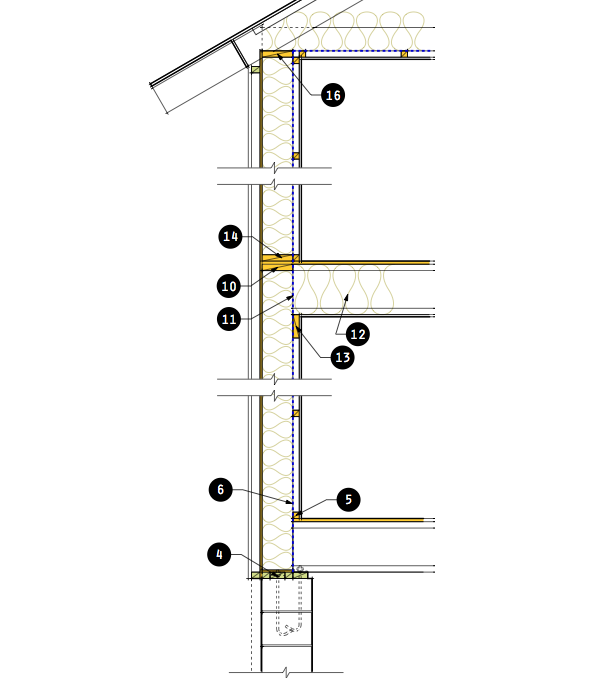
What we are going to look at is how SPF framing improves thermal performance over WPF, and how SPF lends itself to off-site construction better than WPF. We'll hit those points at each step. Behold, the Swedish Platform Frame, in all its glorious simplicity. Seeing the wall system in its entirety makes clear the importance of the wiring chase. This element contributes the essential mechanisms by which the wall can be made air-tight and thermally improved.
Lets start at the top of the foundation at the sill plate. Looking at the illustration below on the left we have the Western Platform Frame. The sill plate(1) is anchor bolted to the foundation, and in quality construction you would find two 2x6 sill plates. Since quality construction is rare today you more often see one sill plate. With one or two these sill plates form a thermal bridge to the exterior. Typically they are only covered by sheathing and siding to the exterior, and unless the basement is finished they are exposed to the basement side. The joists rest on the plates and are capped by a rim joist(2) and topped by deck. This rim space is often poorly insulated and is one of the situations that helped batt insulation make such a bad name for itself. Its often impossible to establish the vapor retarder/barrier line here, and combined with penetrations for hose bibs, dryer vents, hvac vents, this rim space often leaks like hell. Not to mention that it is completely discontinuous to the vapor barrier above the floor, if there even is one. Basically it is almost impossible to make an airtight barrier using a vapor retarder here, so either it has to happen someplace else or it does not happen at all. Above the deck there is a sole plate(3) for the first floor wall, which all the studs land on, and this makes an additional thermal bridge. Lets count them - with our double sill plate we are up to 3, and we've not gotten off the first floor yet.
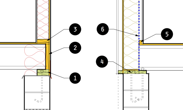
On the right is the Swedish Platform Frame wall. In Sweden the off-site built ground floor wall will come out to the site in one piece that extends from the foundation to the second floor level. So what we have at the foundation is a "split-sill"(4). This is one 2x4 sill plate centered on the wall above (2x8 walls) or equal to the interior half of a full depth sill plate (2x6). Attached to the wall is a plywood plate, with the rest of the sill plate. This is like a tongue and groove joint, which allows our anchoring, and the sole plate of the wall above to be one in the same. It also permits the wall to be positioned precisely on the foundation when the sill plate is installed, not when a wall panel is dangling from a crane. The wall keys into the sill plate and its in the right position. If you were site building this you would use a solid sill. Inboard of this is a sill plate for the floor joists. Walls using an interior wiring chase tie the joists to the studs using the first 2x2 furring member(5). Walls without the interior wire chase use a rim joist, or ribbon tie let into the joists tops as is common with plate nailed floor trusses. Ok. Did we follow that? One sill plate. No sole plate. No rim joist insulation space. Wall batts continue all the way to the sill plate uninterrupted. The vapor retarder/barrier(6) also continues all the way to the wall sill uninterrupted. This is huge when you are trying to create a continuous vapor retarder, and huge that we can make a consistent insulation cavity all the way to the sill. And we are keeping count of thermal bridges, right - 1.
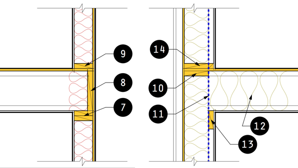
Next up is the second floor, because we might as well assume this is a two story house. Western Platform Framing to the left again. What do we see? Top of the first floor studs are capped with the top plates(7). Convention is two top plates which allows the floor joists to be spaced independently of the studs below. Of course so called "Advanced Framing" tries to eliminate the second top plate, but to do so imposes a rigid grid, and so few builders adopt the system. Second floor joists and another rim joist(8) top the plates, and create another notoriously difficult space to insulate. Vapor barriers are difficult to establish here, and its a prime site for condensation problems and mold in poorly built houses. The floor deck tops the joists making our second floor platform where the second floor wall begins again with another sole plate(9). What is our thermal bridge count now? 3 more + 3 = total 6.
What's going on over at the Swedish Platform Wall? Here our walls studs are not stopping at the ceiling, and instead are continuing all the way up to a top plate(10) that is even with the top of the second floor joists. Hows that? This does two things for us. First it allows the insulated wall cavity to extend past the floor joists again - no rim space. It also allows the vapor retarder/barrier(11) to extend all the way to the second floor deck where it can be neatly sealed off. The Swedes fill their floor joist space with full depth insulation(12) that will extend in about 2ft. This prevents a thermal bridge from the walls top plate. So the first thing this is doing for us is improving thermal performance and air-tightness of the vapor retarder/barrier. The second thing is does for us is extend the finishes of our off-site built wall all the way to the second floor wall panels. Look over at the Western Platform Wall and imagine you just craned in your wall panels for the second floor. You will have a strip equal to the depth of your floor with no exterior finishes that you need to clad, and flash, and seal. Not so for the Swedes. A simple flashing joint, sometimes a horizontal trim piece. No fussing with "stitching" up. But how about the floor joists? What is holding them up? The Swedes use a ledger board(13) in the wiring chase that keeps the joist bearing and the end of the joists all inside of the vapor retarder/barrier line. No struggle to seal a barrier to the side of the joists, no thermal bridge from the joist ends. We are not done yet. On top of the second floor deck we have the sole plate(14) for the second floor wall, and it does form a thermal bridge with the furring member at the bottom of the wire chase. Well we have to take our lumps - what is our thermal bridge count now? 1more + 1 = total 2.
Next stop, second floor ceiling, and then we are done.
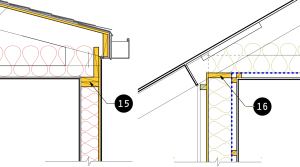
On the left the Western Platform Frame wraps up the second floor wall with two more top plates(15). Ceiling joists and roof rafters land on these and attic insulation occurs above the ceiling. Not too much to say here, but remember that every hole in the ceiling becomes a hazard for air leakage and erodes the energy performance of the house. And we've added two more thermal bridges. 2 + 6 = 8 total. If we threw them a bone and said Advanced Framing works perfectly here, then the total is 6. But we'll give them only 1, and take the same for the Swedish Platform. Call the total 7 thermal bridges.
The Swedish Platform wall is not markedly different, but it does have the wiring chase continuing across the ceiling. This again allows the vapor retarder/barrer to continue uninterrupted completing our effort to make an airtight house. The wiring chase also creates a buffer to the top plate(16) of the wall preventing a thermal bridge. So that leaves our thermal bridge total unchanged at 2.
Overcoming this horizontal thermal bridging is the key to improving the performance of stud framed walls. Its why Advanced Framing Methods only make a middling improvement over Western Platform Framing, and its why most other wall systems become hopelessly complicated trying to break these weak links. The Swedish Platform Frame is over three times better than the Western Platform Frame wall in horizontal thermal bridging, and and that is without even considering the external and internal insulation layers that further improve the wall performance. This is why the Swedish Platform Frame is the next evolutionary step in stud framing. We need to commit to building better energy performance into our homes. This framing method is the best way to do it. Simplest to build, and the best performance.
Many alternate construction methods are being tried these days. Spray foams and blown in cellulose in conventional walls do not resolve thermal bridging. Double studs introduce more labor, and can not be built off-site without introducing bracing that defeats their thermal break. These other methods are valid and they certainly can be executed successfully, but they require the builder to take on new trade activities and stray into unfamiliar ground. New sub contractors, new routines, unknown cost factors, more risk. All barriers to wide spread adoption of alternate wall systems. The USA new wall can be adopted incrementally, allowing a builder to take small steps to improving the performance of his construction. Good, Better, Best, as his comfort level and experience increases they can forge a path to improving the quality and energy performance of their product. For the vast majority this is the way forward, just as its already come to pass in Sweden.
--
Appendix: Comparing the USA New Wall to double stud walls.
This question has come up so I thought it was worthwhile addressing it now when the wall system was introduced.
The question is don't these walls with bigger studs and additional furrning use more lumber, more material - isn't that bad? Well, yes and no. My experience is that all high performing walls use more material. There is really no way around that.
Double stud walls have been promoted as a way to have your cake and eat it too. Two cheap 2x4 walls with as much space between them as you want for more insulation. The downside is, the further apart these walls get, the more bracing and strength you have to add. Furthermore, a double stud wall can' be fabricated as a wall panel off-site. And you can't get away from the doubling of labor for framing a wall twice. The furring strips on the USA New Wall are much simpler to add to a single stud wall than framing a second wall with sill and head plates, and provides the same beneficial thermal break. There is no getting away from it - double stud walls equal more labor.
But how about material? I've done a quick board ft comparison of a 2x8 USA New Wall to an Advanced Framing double 2x4 stud wall. For an 8ft length of wall, two story wall section, with 8ft ceiling heights, my calc put the double stud wall at 107.25 bdft, and the 2x8 framed USA New Wall at 111.5 bdft. The difference amounts to one 9ft 2x4. Omitted from this calculation was the sill plate. If the Advanced Framing double stud wall used 2 sill plates, then the USA New Wall will actually use slightly less lumber. If window framing introduces one additional jamb stud to the Advanced Framing system, the two walls are equal. Note the USA New Wall does not suffer the constraints of the Advanced Framing Wall for window openings. Double Stud Walls offer no advantage of less material. Double Stud Walls using Western Platform Framing with additional horizontal plates will have more lumber than the 2x8 based USA New Wall. And the 2x6 based USA New Wall has less lumber than any double stud wall. I can assure you that if a double stud wall added up to a more efficient building method, then Sweden would be building double stud walls. This question has already been vetted. The results are 30 years old.


very intriguing posts L. lately, your blog has been giving that buildingscience.com website a run for its money. some good stuff to ponder.
ReplyDeleteany projects on the boards to put this forthcoming hybrid USA/Swedish wall to the test in any of your future projects?
You are very kind, but this is nothing like the research that BSC does.
ReplyDeleteI have one active project now considering an application of the new wall, but not with the swedish platform frame.
Greg,
ReplyDeleteYou've been busy! Great graphics and analysis. Very thought provoking. Are there any single stud, site built solutions that you've discovered in your research that Sweden is constructing?
A few Swedish house manufacturers actually site build, but they build the same kinds of walls as the factory builders.
ReplyDeleteHi Greg, cool assembly! If site built what is the sequence of construction especially with regard to installation of air vapor/retarder film.. Walls then joists? Would AHJ require fire/smoke blocking at top of wall below the fjs? or do yo think the sill plate is sufficient?
ReplyDeleteThe truss-joist literature I have requires minimum 1 3/4" end bearing. This would require non-standard size of lumber.
The sequence is not straight forward. The bottom of the walls needs to have the retarder installed before the floor joists are in place, and then the top flap of that can be taped to the rest of the wall vapor retarder when it is installed. The same two part step needs to happen at the top of the ground floor studs where the second floor joists are. This is why the wall works much better built off site, or even on slab on grade instead of a basement.
ReplyDelete1.5" of bearing is fine for small spans and light loads such as in a house, despite what the manufacturers may say. I'm sure they will be happy to certify that 1.5" bearing is ok for given spans and loads whenever builders start in building thousands of houses this way ;^]
With the exception of some of better detailing the sill plate & floor joist & band joist this approach is very similar to a "Mooney Wall" approac, using 2x8 studs (rather than the more common 2x4 & 2x6 Mooney Walls.) BSC did a fairly careful analysis of a 2x6 Mooney wall in a high performance wall document here:
ReplyDeletehttp://www.buildingscience.com/documents/reports/rr-0903-building-america-special-research-project-high-r-walls
See the analyses for Case 3.
See also:
http://www.builditsolar.com/Projects/Conservation/MooneyWall/MooneyWall.htm
Most US Mooney walls are usually built without a vapor retarder or air-barrier at the furring/stud plane, opting instead to detail the exterior sheathing as the primary air barrier. For much of the US (Zones 1-5, inclusive) interior side vapor barriers are not necessary if the wall assembly is built with back-ventilated siding/rainscreen, and Zone-6 even qualifies if the exterior sheathing isn't wood, but rather a fiber-board/gypsum type. (GP DensGlass, etc.)
While there's nothing inherently wrong with using the furring/stud plane to place a vapor barrier or air barrier, it's more difficult to air-seal penetrations at that layer that are made after the fact, and making it a vapor-permeable or semi-permeable material would enhance the drying capacity with no or very low risk the sheathing in most of the US (including the relatively mild NJ climate.)
Here we go. Well sooner or later I had to address this here so it may as well be now.
ReplyDeleteAnonymous, Yes, I am very familiar with that BSC study, and I've looked closely at the trials case you reference - Case 3, Interior strapped wall. I have to emphasize it is not similar to the Swedish Platform Framing that I am presenting. Aside from the fact they have used an interior cross furred insulation space very little is similar. BSC's sample wall uses "Advanced Framing" and hence still has a large number of horizontal thermal bridges which decreases its performance. This is borne out by their test data. In any case that test data has little bearing on the performance of the wall assembly depicted here, and their test methodology did not take into consideration a second floor bearing condition, nor a roof bearing condition - both are places where the Swedish Platform Frame significantly outperforms the Western Platform Frame based "Advanced Framing."
Let me say it plainly: That BSC assembly is not this wall. Don't be quick to dismiss the differences because you will be overlooking some carefully considered decisions that shape the way they it is framed and performs.
I also have to disagree with several of your conclusions however. The interior vapor retarder, or barrier is very easy to make an air-tight house with. Penetrations through barrier are limited to exhaust vents and hvac fresh air intakes. No different that sheathing based locations. I also disagree with the growing conclusion that the exterior sheathing is now the place to make a vapor barrier or retarder. This is contrary to decades of building rationale, and as I've elaborated elsewhere in heating climates this requires much more analysis before you can be certain of where your dew point falls. Builders and contractors don't make this analysis - they build "standard" wall configurations that must be resilient for different conditions. Exterior vapor barrier/retarders in heating climates with walls drying to the inside require certainty about where and when moisture can condense in that wall. This is fine for a custom designed "Green House" but not for a prototype wall to be widely adopted.
Zones 1,2,&3, vapor barriers should be towards the exterior and the wall designed to dry to the interior. These are clearly cooling climates, with only mild and short lived winter conditions.
ReplyDeleteZones 6&7 you are foolish to deviate from the tried and true vapor retarder/barrier to the inside. If you put it on the outside you need to examine the wall's vapor profile precisely to be sure your dew point remains outside the wall cavity. If you are zone 6 and with air-conditioning you should use a smart retarder like membrane which will adapt to summer conditions. You should also keep the outside of the wall relatively tight to keep summer air out of the wall. This means at least housewrap, but a taped sheathing layer is probably too much and will retard winter drying of the wall. If you have no air conditioning is zones 6 or 7 then you should have a full on vapor barrier at the interior, and strive to keep your wall as open as feasible to the exterior. That means no taped sheathing, lapped building paper rather than housewrap. This maximizes winter drying potential for the wall cavity, and maintains the house airtight at the interior vapor barrier. This is in fact the model Swedish wall.
Most of zone 4 is transitional. Hot summers, much of the range moist, but also prolonged winter conditions. This is a zone that benefits from walls that can dry to both sides. This wall configuration can take on many forms. You can put the primary vapor retarder to the outside, but you must be careful you don't set the wall up to fail in winter. The best strategy is to pick a side for your air tight layer. Keep the other side tight, but not an air sealed layer. In zone 4 you have to know your local climate and design for it appropriately.
Now Zone4 has the greatest variety. I'm at the northern end of Zone4 in Philadelphia, and I would never recommend an interior drying wall here. We have hot humid summers, but cold winters that can spend a week in the teens. I would follow a profile here that is more similar to a Zone 5 wall. Smart vapor retarder to the inside as the primary air seal, and a relatively tight exterior, but not sealed. Its a winter biased wall profile, that resists moist air entering the wall in summer, and a smart vapor barrier to dry the cavity if summer moisture does condense inside.
The USA New Wall profiles shown are only heating climate configurations. Zone 5,6,7, & some locations in zone 4. They are designed to be resilient, and not precise. Something that builders can adopt without doing a complex analysis. Because most of what gets built has none of the benefit of an architect or building scientist. If we are going to offer advice, lets make it advice that makes it hard to fail, instead of requiring precision to succeed.
I strongly disagree with blanket recommendations for exterior located vapor retarders in heating climate walls, and I want my readers to be cautious of this. This is a building science FAD, and one that I'm afraid will be widely applied without the proper understanding and give us our next building failure debacle. I see a lot of poor advice being handed out in this regard on the internet. Don't take advice for an interior drying/exterior located vapor barrier without being quite certain how it will interact with your climate. That wall needs to be designed.
To go back to wright's comment above regarding bearing: as right as you may be about 1.5" of bearing be sufficient, I wouldn't detail a structural component in direct contradiction of the manufacturer's requirements. That would leave me more exposed to liability than I care to be.
ReplyDeleteHave you considered using hangers rather than bearing directly on the ledger?
I think that a configuration using a ledger with metal joist hangers is a great idea.
ReplyDeleteLook - these walls are open source. You are encouraged to re-mix and make adaptations.